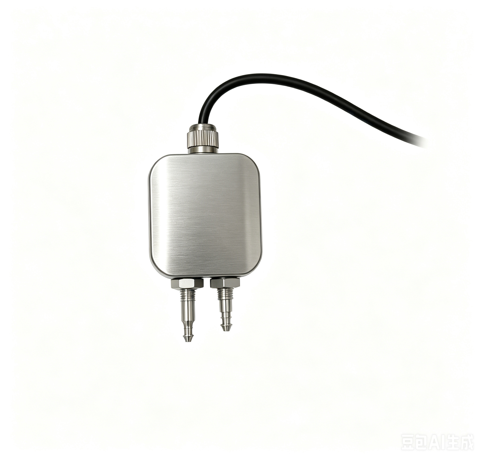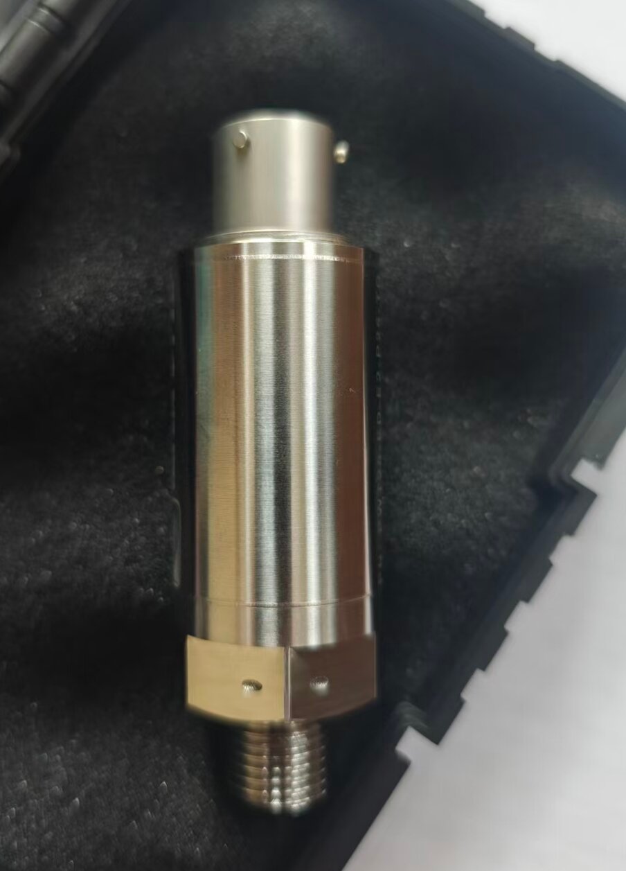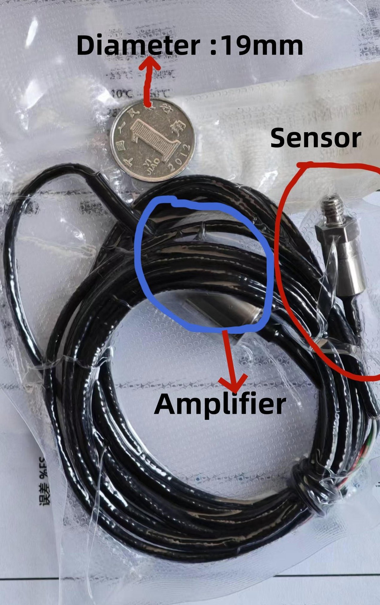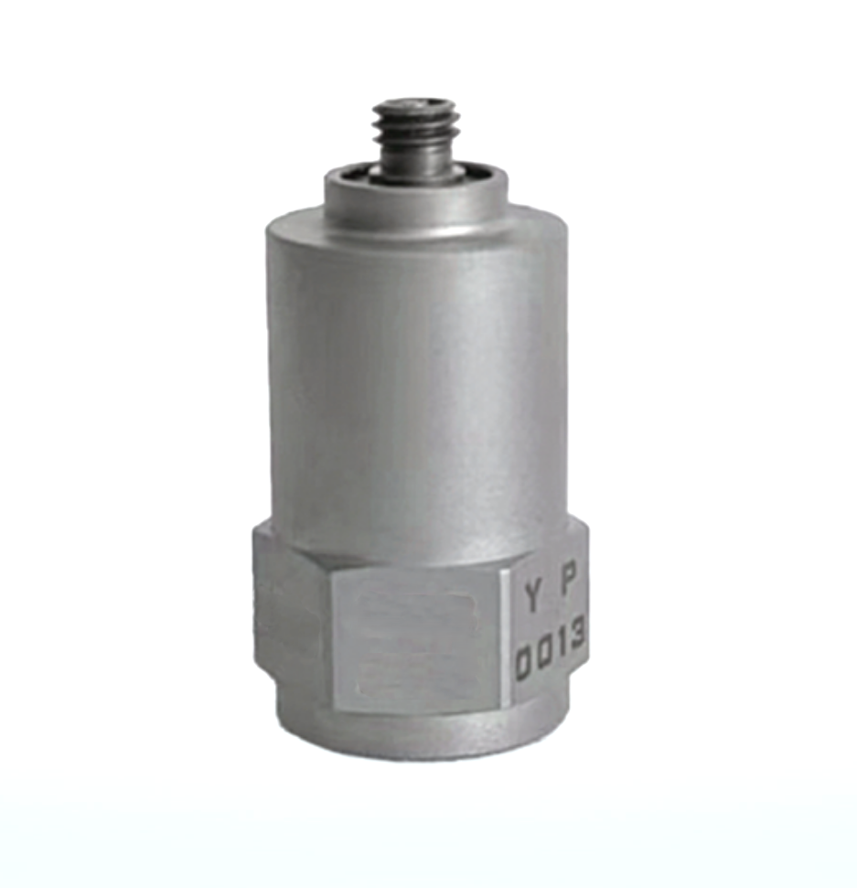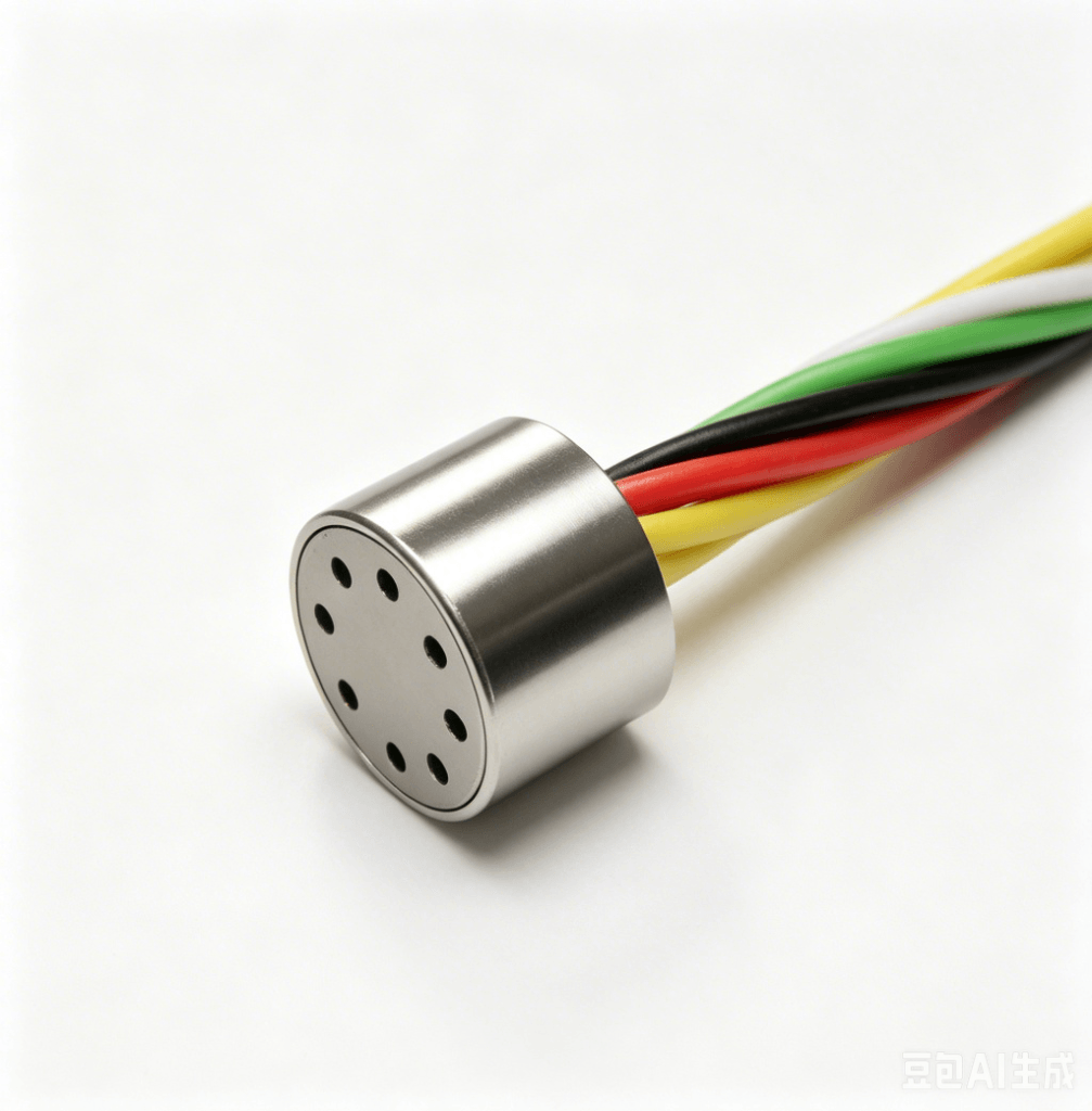
When pressure has to be measured inside a probe, a rake, a wind tunnel model, or a compact test rig, a standard transmitter will not fit. That is when engineers look for an ultraminiature pressure transducer — and where a few specification decisions determine whether the sensor disappears into the design or becomes a recurring maintenance problem.
This guide covers what to specify, how the Dabey UPT200 compares with the Kulite XCQ-062 class, and which installation errors cause most field failures.
Quick answer: The UPT200 is a 10 mm piezoresistive pressure transducer with nine ranges from 5 to 1000 PSI, 100 mV bridge output, and natural frequencies from 150 to 1000 kHz. It is built for probe, rake, and test-rig assemblies where space and mass are limited.
What “Ultraminiature” Means
An ultraminiature transducer is a piezoresistive element packaged small and light enough to mount on or inside the structure being measured, without changing how that structure behaves. The UPT200 uses a 10 mm body, a 4-arm Wheatstone bridge, and an all-stainless-steel housing.
Three consequences follow:
- Low mass, small frontal area. On probe arrays and instrumented models, sensor weight shows up as measurement error and as fatigue load on the mount.
- Fast response. Small diaphragms with minimal oil volume reach high natural frequencies, so one sensor can capture static pressure and fast transients.
- Tighter margins. Less thermal mass, fewer mounting options, lower torque limits. Small sensors must be specified carefully.
Where They’re Used
- Aerospace and fluid mechanics testing — pressure rakes, probe assemblies, model surfaces
- Impact dynamics — fast transient capture
- Research laboratories — dense multi-channel arrays
- Energy and power — compact rigs and benches
- Industrial automation — high-cycle OEM equipment
Seven Specs That Decide
1. Range
The UPT200 covers nine ranges from 0.035 to 7 MPa (5 to 1000 PSI), with overload above 2× and burst above 3× full scale. Keep normal operation in the upper-middle of the span, and check overload margin against real transients — valve slam, water hammer, pump start-up — not against steady-state pressure.
2. Reference Type
Absolute, gauge, and differential options run across the lineup, with sealed gauge at mid ranges and absolute/sealed gauge combinations at the high end. The choice affects both accuracy budget and plumbing.
3. Output and Excitation
A 4-arm Wheatstone bridge delivers 100 mV typical full-scale output at 10 VDC rated excitation (12 VDC maximum). Bridge output gives high sensitivity and full control at the DAQ end, but demands stable excitation and clean shielding.
4. Accuracy
The UPT200 is rated at ±0.1% FS typical and ±0.2% FS maximum for combined non-linearity, hysteresis, and repeatability. On multi-sensor arrays, budget with the maximum, not the typical.
5. Thermal Behavior
Zero and sensitivity thermal shift are quoted per 100 °C by some manufacturers and per 100 °F by others — these are not interchangeable. Because 100 °C equals 180 °F, multiply a per-100 °F figure by 1.8 before comparing.
The UPT200 runs from -40 °C to +125 °C, with a standard compensated range of 20 °C to 85 °C and customization to any window inside the operating limits. Match the compensation window to your real media and ambient conditions.
6. Impedance
Input impedance is greater than 4000 Ω and output impedance is 5000 Ω typical. High input impedance draws less current from the excitation supply — useful when several sensors share one supply in a rake. Higher output impedance also means the receiving instrument must have high input impedance, or the reading will be loaded down. Check your DAQ front end before fixing the channel count.
7. Mechanical Limits
Shock and vibration are rated at 20 g, covering sine 10–2000 Hz and half-sine ≤ 20 ms. Standard connection is a 4 × 36 AWG ribbon cable at 1000 mm, with a 6-wire option (600 + 300 mm).
UPT200 vs. XCQ-062
Compiled from manufacturer datasheets. Thermal coefficients normalized to a per-100 °C basis. Trademarks belong to their respective owners; shown for engineering identification only.
| Parameter | Kulite XCQ-062 | Dabey UPT200 |
|---|---|---|
| Pressure range | 0.35–70 bar / 5–1000 PSI (9 steps) | 0.035–7 MPa / 5–1000 PSI (9 steps) |
| Operational mode | Abs / gauge / diff (low); + sealed gauge (mid); abs / sealed gauge (high) | Abs / gauge / diff; + sealed gauge; abs / sealed gauge |
| Overload / burst | 2 × / 3 × rated | > 2 × / > 3 × FS |
| Rated / max excitation | 10 / 12 VDC-AC | 10 / 12 VDC |
| Input impedance | 1000 Ω (min) | > 4000 Ω |
| Output impedance | 1000 Ω (nom) | 5000 Ω (typ) |
| Full-scale output | 100 mV (nom) | 100 mV (typ) |
| Zero offset | ± 5 mV (typ) | ± 5 mV (typ) |
| Accuracy | ± 0.1% FSO BFSL (typ); ± 0.5% FSO (max) | ± 0.1% FS (typ); ± 0.2% FS (max) |
| Natural frequency | 150–1000 kHz | 150–1000 kHz |
| Acceleration sensitivity | 1.5e-3 → 4.5e-5 %FS/g | 1.5e-3 → 4.5e-5 %FS/g |
| Insulation resistance | 100 MΩ min @ 50 VDC | > 100 MΩ @ 50 VDC |
| Operating temperature | -55 °C to +120 °C | -40 °C to +125 °C |
| Compensated temperature | 25–80 °C (custom 100 °F window) | 20–85 °C (custom any range) |
| Zero thermal shift (per 100 °C) | ± 3.6% FS (typ); ± 1.8% FS (high range) | ± 3% FS (typ); ± 1.5% FS |
| Sensitivity thermal shift (per 100 °C) | ± 3.6% FS (typ); ± 1.8% FS (high range) | ± 3% FS (typ); ± 1.5% FS |
| Shock / vibration | 20 g half-sine, 11 ms; 20 g peak, 10–2000 Hz | 20 g, ≤ 20 ms; max 20 g, 10–2000 Hz |
| Weight (excl. module and leads) | 0.2 g (nom) | 0.6 g (typ) |
| Electrical connection | 4 × 36 AWG, 914 mm | 4 × 36 AWG ribbon, 1000 mm (6-wire option) |
XCQ-062 thermal values converted from per-100 °F to per-100 °C (×1.8).
How to read it:
- Normalize units first. Thermal data is only comparable on one temperature base.
- Accuracy definitions differ. One datasheet uses BFSL, the other states FS. They are not the same calculation — ask which definition applies.
- Impedance is a system property. Higher input impedance eases the excitation supply; higher output impedance shifts the requirement to your instrument.
- Temperature coverage differs at both ends. One reaches -55 °C; the other reaches +125 °C. Match your environment.
- Weight is not equal. 0.2 g against 0.6 g is not a large number, but on a mass-critical balance or a light probe, evaluate the difference rather than assuming interchangeability.
Choosing between them? Send your range, reference type, output, temperature window, and mounting constraints. Our applications engineers will confirm the closest UPT200 configuration and return the datasheet and dimensional drawing. Talk to an applications engineer →
Replacement Checklist
- Thread, body diameter, insertion depth, sealing surface
- Diaphragm and wetted materials against your media
- Reference type — absolute, gauge, sealed gauge, differential
- Range, overload, and burst margin
- Output type, full-scale value, sensitivity
- Excitation voltage and impedance matching your DAQ
- Operating and compensated temperature windows
- Sensor weight against your assembly mass limits
- Cable length, wire count, connector
- Calibration documentation and dimensional drawing
Treat “drop-in replacement” as the opening of an engineering review, not the conclusion. Fit can be confirmed from drawings; function should be confirmed with a side-by-side test in your own fixture.
Installation Pitfalls
- Over-torquing a small body. Use the specified torque and a calibrated wrench.
- Sealant on the diaphragm. Follow the specified sealing method; do not add compound.
- Side-loaded cable. Add a service loop and strain relief. Vibration plus a rigid run fatigues the joint.
- Trapped air in liquid lines. Mount where gas can escape, and bleed before commissioning.
- Ground loops. Shared grounds with drives and contactors appear as unstable zero on bridge sensors.
- Reused cable. A cracked jacket becomes an intermittent fault, then a permanent one. Replace cable and sensor together.
Maintenance Basics
- Verify zero at scheduled shutdowns, at a known condition and ambient temperature.
- Calibrate against a traceable reference on an interval set by criticality and cycle count.
- Inspect seal, threads, and corrosion each time the sensor is removed.
- Log ambient temperature and transient events alongside the reading.
- Standardize on one or two models per site to simplify spares and training.
Bottom Line
An ultraminiature pressure transducer is a packaging solution with a measurement specification attached. Get the range, reference type, output, accuracy definition, thermal window, and impedance right, and it becomes invisible in the system. Get the installation wrong, and a technically sound sensor produces months of unexplained readings.
CTA
Talk to an applications engineer.
Send us your pressure range, reference type, output requirement, temperature window, and mounting constraints. We will confirm the closest UPT200 configuration and return the datasheet, dimensional drawing, and calibration options.
Talk to an applications engineer → · View the UPT200 product page →
FAQ
What is an ultraminiature pressure transducer?
A piezoresistive pressure sensor packaged small and light enough to mount inside probes, rakes, and compact test assemblies without altering the behavior of the structure being measured. Typical traits: low mass, high natural frequency, static and dynamic capability.
What ranges does the UPT200 cover?
Nine ranges from 0.035 to 7 MPa (5 to 1000 PSI), with overload above 2× and burst above 3× full scale.
Can it replace a Kulite XCQ-062?
Fits can be checked from thread, diameter, sealing surface, and insertion depth. Function depends on range, reference type, output, excitation, impedance, temperature compensation, and weight — the UPT200 is 0.6 g typical against 0.2 g nominal. Since accuracy and thermal figures use different definitions and temperature bases, validate side by side in your own fixture.
What output does it use?
A 4-arm Wheatstone bridge with 100 mV typical full-scale output, 10 VDC rated excitation (12 VDC max), input impedance above 4000 Ω, output impedance 5000 Ω typical. Pair it with high-impedance instrumentation.
Per 100 °C or per 100 °F — which applies?
Both appear in the market and cannot be compared directly. Since 100 °C equals 180 °F, multiply a per-100 °F coefficient by 1.8 to express it per 100 °C.
How often should it be calibrated?
Based on cycle count, transient severity, temperature extremes, and measurement criticality — not on a fixed calendar default. Many teams start annually and shorten the interval once drift is observed.